
I use the Viessmann 5210 signal modules to control my signals, and I have all those modules in one area under the layout. This is done to reduce the number of 5211 modules needed to drive 5210 modules.
See http://layout.mixmox.com/1/signals-1 for more information on that subject.
Since the location of the 5210 control modules is thus some distance from where the signals are to be installed on the layout, they need long cables to reach the signals. This is why I solder the signal leads onto multi-strand electrical cables before installing.
The first thing I do is to test the signal is working correctly. I have never had a bad signal but I know that if one was defective it would save me time to find out before I install it, vs. spending time troubleshooting my wiring and control systems before isolating a problem to the signal itself. Viessmann supply their signals so that they can be tested before being removed from the box!
Here a distance signal is being tested by applying 12 Volts DC. Connect the positive supply to the lead with the diode and marked with a black color. Attach the negative to each of the other leads in turn, each lead should make one light on the signal illuminate. For signals that have more than one lead with the same color, this is the time to mark which is which. For example the distance signals have two greens and two yellows. I note which ones are for the top lights and mark their resistors with a green marker. For signals with two red lamps, I mark which one is the leftmost one.

Since I am also reinstalling signals that were removed from my previous layout, I thought that testing was more important than usual. Here I am testing a block Hp signal that has already been desoldered from the previous installation.

Next, I cut a length of cable that will be long enough to get from the signal to the signal control area. Do not underestimate the length needed. If in doubt, you should actually pull the cable through to ensure that the length is long enough, then cut it and remove. If I have other signals to install in the same area I use the first length to measure off the next length, but I do not cut the second one until I have installed the first and I know if any adjustment may be needed.
I use telephone cable or CAT-5 computer network cable. Some complex signals have 6 wires and so you need to use a cable that has at least 6 wires. Some cables have just 4, some 6 and some 8. Some signals have just 3 wires and can thus use 4 stranded cables.
I bring the cable to the workbench and strip back the cable sheath about 6cm and strip the insulation off the wires I need. The colors of the wires do not matter of course, but I use wires that best match the signal wire's colors. The wire I am using has blue, orange, and green pairs, so I use blue for the positive wire and, orange for the red aspect and green for the green aspect etc. Stay consistent or write it down, or both.
In order to hold the cable nicely, I clamp it to the edge of my desk.
Onto each wire I slip a short length of heat shrink tubing (1/32") slightly longer than the stripped wire length.

I then tin each wire with some solder and then solder each signal lead onto a wire.

Once all the leads are connected I test the signal again from the other end of the cable. This ensures that the cable and its connections are all good. (I often used second hand cable and have had a case where one lead was bad!)
Once that test is done, I cut off the stripped end (that was used for testing) at an angle to enable easy threading through holes.

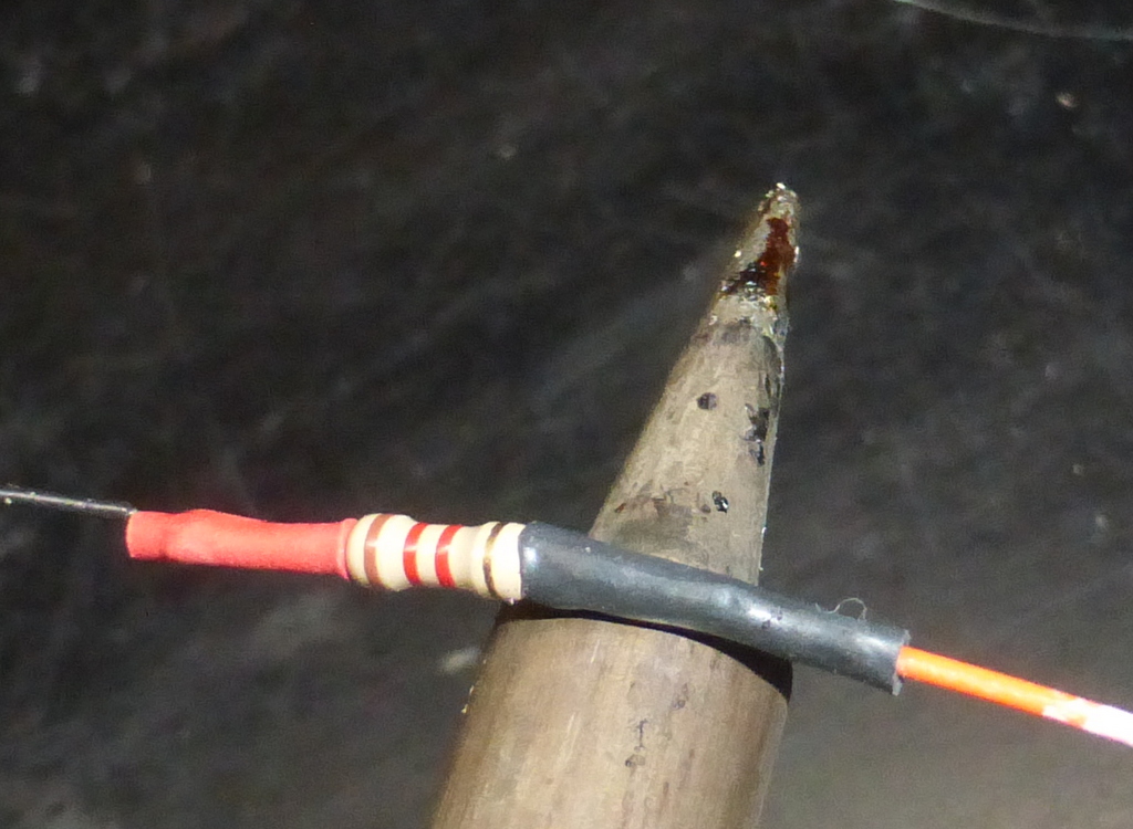
I slide the heat shrink tubing up over the soldered joints and heat them up with the shoulder of the soldering iron.
Do not cover the resistors with the heat shrink tubing as they need to be able to dissipate heat well.
I drill the hole in the layout for the signal using a 6mm drill bit (or one as close to that size as possible). I check what is below the layout surface to ensure I do not run into electrical wires, brackets or thick supports and find a location for the signal (to the right of the track) that is reasonable. I try not to locate them too close to the edge of the layout where they may be easily bumped. Within the reasonable limits of prototypical placement, I also try to place the distance signals in a position that I can see their aspect from my control area if I am unable to see the main signals itself. This provides me with additional visual feedback on what is happening on the layout!
I then thread the long length of cable through the hole in the layout. Note that signals with many wires need to have their connections staggered so that all 6 connections with the lumpy resistors are not being forced through the hole together. I pull some wires through ahead of the others.

The signal is then stood in its hole

Since the signal wires are very fine, I secure the end of the long cable so that pulling on the cable will not place any strain on the signal wires and connections. I leave enough slack in the wires to allow the signal to be lifted out a short distance, and accurately positioned later.

I then thread the cable along under the layout to the area where the 5210 modules are. I cut the cable down to an optimal length, meaning that I have about 20cm spare to allow me to work on the end.
I attach plugs to the end of each wire and plug them into the module as directed by the Viessmann instructions. Here a simple 2-aspect block signal is being driven by the left hand side of the module.
(I have previously connected the DT and L+ terminals by adding a wire inside the module since that sets the module to operate two signals independently)

I then power on the layout. The newly inserted signal should display aspect-0.
I then test that activating the Märklin k83 or Viessmann 5211 modules that drive the 5210 module do, in fact, change the signal aspects. If they do not, it is usually a matter of ensuring that the outputs of the k83 are properly plugged into the 5210 module. If the signal does not light up at all it will either be the power connection to the 5210 module (+ and - ) or the L+ connection to the signal.
I then configure the addresses needed for each aspect in my software.

Once I know it is all working I can then make the position of the signal permanent. I place a small amount of wood glue onto the socket of the signal base and then hold it in place with a small clamp.

When installing multiple signals in line, I glue them all in place at once to ensure that they are properly aligned. To do this I clamp them all onto a small piece of wood, getting them all vertical and at the same height.

The human eye detects things that are not straight very easily, especially when they are points of lights such as LED signals, so I take care to ensure they are as close as possible to being straight.
(Note that signals must be installed in a straight line across the tracks when there are curves in the track that would allow the signals to be seen in the wrong order from anywhere ahead of them.)

Once they are well lined up I add the glue and then insert them, and recheck their positions.

I find that signals add a great element of interest and animation to the layout!
