Advantages of these modules are:
- You can use momentary contact decoders (k83) type instead of K84s
- Once a signal aspect is selected, it is latched (held) by the module
- Each module can support two signals (up to a 3 aspect plus a 4 aspect)
- It has the ability to handle the Dunkelschaltung of German distance signals on the same pole when the Hp signal is on aspect 0
- It can use 16 VAC or DC input
- The signal lights fade out prototypically
Once set up on a sheet of plywood, the whole assembly is then mounted on the wall under the layout.

I then bring the cables from the signals to the panel and plug them into the lower edge of the 5210 modules.
The Dunkeschaultung is on by default. To suppress it one has to connect the two posts indicated by the black arrow. I would have preferred the switch to be the other way, since I mostly drive two signals with each module and having the distance signal on the same pole as the main signal is more of an exception. What I do is open the cover and solder a wire between the two ports so I don't have to fiddle about with another external wire and two more plugs.
The plugs that Viessmann supplies with their modules are not very good. I prefer those from Märklin (old style) or from Conrad or Brawa.
Here is an older write up of a bigger installation I did of the 5210 modules from March 2007.
I have chosen to drive my Viessmann LED light signals with the Viessmann 5210 signal control modules. The modules use positive accessory decoder momentary impulse inputs (as produced by K83 type decoders such as the Viessmann 5211) instead of the more expensive k84 type digital relays. In addition they also make the lights fade out and handle all the aspect switching properly. For example to switch from Hp2 to Hp0 one need only to worry about activating the Hp0 input which will switch the red light on and switch the green and yellow lights off.
Each module can handle two signals. One entry signal with 4 aspects (Hp0/1/2 Sh1) plus one other 2 or 3 aspect signal such as a distance signal (Vr0/1/2) or Sh0/1 or block signals Hp0/1.
My layout has 28 signals such that I have 14 pairs of main signals and other 2 or 3 aspect signals meaning I need 14 signal modules. Each module requires 6 different inputs to switch between the various aspects of the two signals controlled by the module. Since k83 type decoders each have eight outputs, three decoders can be used to drive 4 signal modules. This essentially dictated that I should place all my modules in one place so that I could maximize the use of decoders. I had some time ago already installed a combination distance signal and main signal so I decided to leave that on as it was and install the other 13 together.
If a distance signal is on the same pole as a main signal the modules can also handle the prototypical darkening of the distance signal if you control both from the same module. By default each module assumes that it is being used for a distance and main signal on the same pole, so to make the two signals independent one is instructed to connect two particular ports on the module. Since one of those ports would also need to have both signal positive leads connected to it, I decided to solder an internal wire between the two ports for the 12 modules that would be driving independent signals. This means that I will be able to plug one signal into the normal socket and the other into the other socket (which is now electrically connected) rather than having to connect three wires to one socket.
This shows the initial steps of creating the rack of signals modules and decoders. The signal modules and the decoders were build from kits and took 50 hours of soldering under a magnifier. Each signal module requires 277 joints to be soldered! Kits were bought not for the fun of soldering but for economy.
The first step was to find a suitable place under the layout where I would have enough room. I then cut some scrap plywood to size and painted it black. I only had some ¼" plywood so I stapled some ¼" strips of wood on the back for additional strength. I drilled some holes for mounting it to the wall.
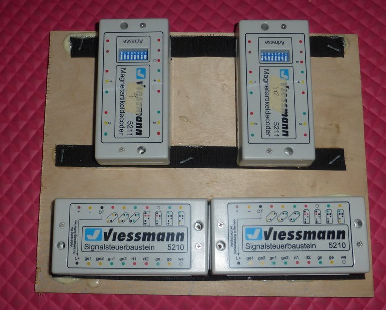
I decided to use Velcro® to hold the modules and wire in place. It seems to be working well. First I glued the furry side to the underside of each module using Liquid Nails® adhesive.

I then glued strips of the hook side to the painted plywood. I also used my staple gun to hold them down - probably overkill.

and pressed the modules in place. I took care to space the modules such that there were three 5211 modules for every four 5290 modules.

Then I could sit comfortably and my desk and connect the decoders with the signal modules

The Velcro provides an easy method of holding the numerous wires in place simply by pressing a short length of Velcro over them.
The signal modules still need to have power supplied to them and of course all the signal cable bundles have to be added.